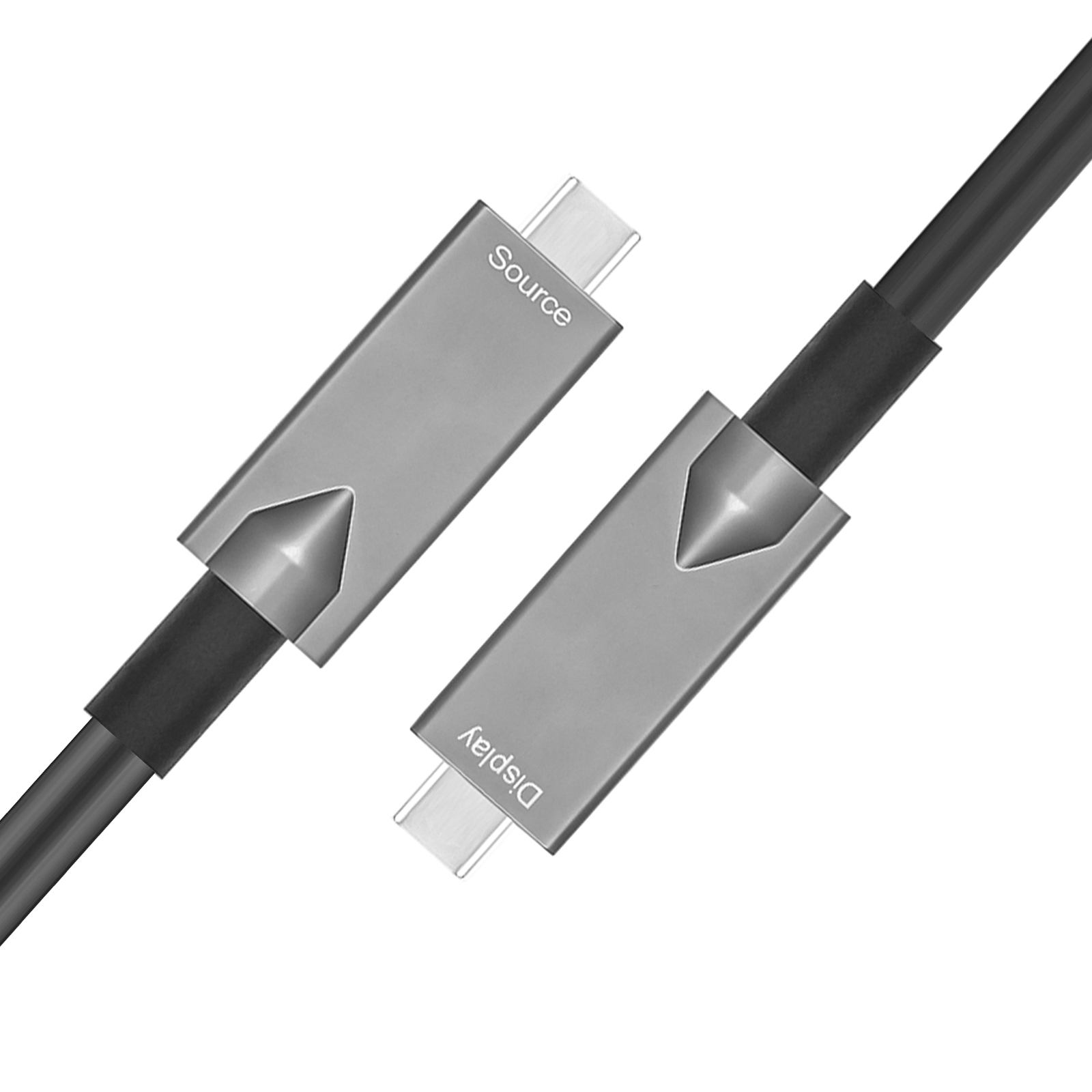
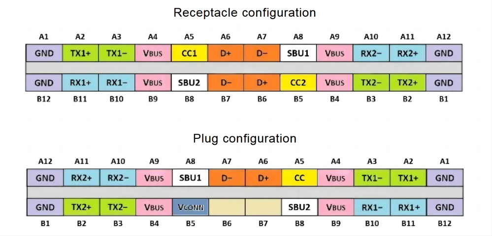
USB Type-C is no longer a new topic, the biggest difference between this USB interface protocol and the Type-A commonly used for notebooks or Micro-B for Android phones is that USB Type-C supports both forward and reverse plugging. With the symmetrical design of 24 pins on the top left and bottom right, half of the pins are available for normal operation for both forward and reverse plugs. The simplest USB Type-C interface, supporting USB 2.0 (D+ and D- in Table 1), adds high-speed signal pairs to support USB 3.1 Gen1 (5Gbps), USB 3.2 Gen2 (10Gbps), and USB 34 Gen3 (40Gbps) transfer speeds (Tx+- and Rx+- in Table 1). In addition, USB Type-C can be through the Power Delivery (hereinafter referred to as PD) protocol, the power supply wattage from the original 5V/3A up to 20V/5A, the current USB-C specification 2.1 revision, but has been 100W whole to 240W (), at the same time, the version after PD 2.0 added Alternative Mode (hereinafter referred to as Alt-Mode), through Alt-Mode can be redefined Table 1 pin definition, so that the USB Type-C connector in addition to transferring data, power, but also to transfer video information. Type-C Connector Type-C connector Science: PIN pin definition of TYPE C connector As USB Type-C can transfer data, power and video, we can see from several newly released flagship cell phones or the latest notebooks that more and more devices are adopting the USB Type-C interface, which has become a trend. The following article will introduce and share the USB Type-C specification in three parts: data, power and video!
USB4 transfer rate increased to 40Gbps
1、Transfer bandwidth: USB4 is 40Gbps maximum.
- Transmission protocol: USB4 encapsulates USB 3.2, DP and PCIe protocols into packets that are sent simultaneously through tunneling technology.
3, DP transmission: USB4 can be configured to output through DP Alt Mode (alternative mode) in addition to the USB4 tunneling protocol packets to extract the DP data.
4, PCIe transmission: USB4 supports PCIe transmission, through the USB4 tunneling protocol packets to extract the PCIe data.
5, TBT3 transmission: USB4 supports TBT3 transmission, that is, through the USB4 tunneling protocol packets to extract PCIe and DP data.
6、Host to Host: communication between host and host, USB4 support. Mainly USB4 support PCIe protocol to support this function.
Note:Tunneling can be seen as a technique to integrate data from different protocols together, distinguishing the types by packet headers.
In USB4, DisplayPort video, USB 3.2 data and PCIe data can be transferred in the same channel, which is the biggest difference between the two. The USB4 lane can be imagined as a lane for all types of vehicles, with USB data, DP data and PCIe data imagined as different cars. USB3.2, DP and PCIe data are first aggregated together, sent out through the same channel to each other’s devices, and then separated out into three different types of data to.
In the past, in order to shorten the charging speed, people increased the output voltage of the charger to increase the charging wattage into the phone. However, because of the inefficiency of the step-down circuit in the phone to convert high voltage to low voltage, the phone gets hot when charging. To solve this problem, we hope to remove the step-down line in the phone, so that the output of the charger is directly connected to the phone battery, the output can be adjusted with the battery voltage changes, so there is a definition of PPS. PPS is like a standard fixed output PD, defined in four standard voltage: 5V (adjustable 3 ~ 5.9V), 9V (adjustable 3 ~ 11V), 15V (adjustable 3 ~ 16V), 20V (adjustable 3~21V ), in each set of adjustable voltage range, the recipient can adjust the power supply for a minimum of 20mV voltage step or 50mA current step according to the current condition of the supply.
If combined with the latest development of the chip maker’s Voltage Scaler for different multipliers at the device side, the battery can be charged at 6A, 9A or 12A with a 3A cable. In addition, in the USB Type-C version 1.3, the new Vconn Power Device (VPD) specification, VPD devices can not only accept the original Vbus power supply, but also accept the minimum 3V voltage provided by Vconn. The purpose of the minimum 3V is that a lithium battery is often placed in mobile devices, and the minimum discharge voltage of a single lithium battery is generally set at 3V. Previously, when power was supplied through the Vbus of the USB interface, the power supply side had to step up the battery voltage to 5V through the boost line, and the receiving side would step down the 5V to 3.3V or 1.8V through the buck chip for other internal chips, resulting in power conversion on both sides and loss of performance. conversion and loss of performance.
Previously, when powering through the Vbus of the USB interface, the power supply side must step up the battery voltage to 5V through the boost line, while the receiving side will step down the 5V to 3.3V or 1.8V through the buck chip for other internal chips, resulting in power conversion on both sides and loss of performance.
If the battery voltage can be supplied directly through Vconn, the overall power conversion efficiency can be greatly improved without the need for other power conversion chips on the power supply or receiving side. As for the E-Marker mentioned earlier, it is placed in both ends of the USB Type-C cable, which is like an ID card for the cable to store information about the cable, including the loadable current (3A or 5A), USB speed (USB 2.0 or USB 3.1), and the cable’s voltage, etc. The power required for the E-Marker is provided by the power supply from Vconn. The power required for E-Marker is provided by the power provider from Vconn. E-markchip
USB Type-C and DisplayPort, PCIE
USB PD is a BMC encoded signal, while the previous USB was FSK, so there is incompatibility, I don’t know if there is a product on the market that can convert. USB PD is transmitted on the CC pin, PD has a VDM (Vendor defined message) function that defines the device end ID, read the device that supports DP or PCIe, DFP will The DFP will enter the alternate mode when it reads the device that supports DP or PCIe. If the DFP recognizes the device as DP, it switches the MUX/Configuration Switch, so that Type-C USB3.1 signal pin can transmit DP signal instead. And DP has lane0-3 four sets of differential signals, Type-C has RX/TX1-2 is also four sets of differential signals, so no problem to replace completely. If the DFP recognizes the device as DP, it switches the MUX/Configuration Switch to let Type-C USB3.1 signal pin to transmit PCIe signals. Similarly, PCIe uses RX/TX2 and SBU1 and SUB2 to transfer data, and RX/TX1 to transfer USB data. The advantage of this is that one interface uses two devices at the same time, and of course, the conversion cable can do it without any chips.
Summarize our understanding
USB Type-C by virtue of the advantages of the connector to kill the jungle, has been successful soon to top, a variety of fields of application unstoppable trend, Apple’s MacBook more let people know the convenience of the USB Type-C interface, but also let everyone see the future development trend of the device, in the next few days, USB Type-C devices will continue to come out; USB Type-C interface will undoubtedly gradually popularize and reign in the next few years, and in cell phones, tablets and other mobile devices, it has several features that allow cell phones to charge faster, have higher data transfer speeds, support display output, more suitable for mobile devices as the output interface, the most important, there is a great need for a universal universal interface to enhance the connectivity between various devices, and USB Type C connector provides a reversible plug-in interface; the socket can be inserted from any direction for easy and reliable plugging, the connector also needs to support a variety of different protocols, can use the adapter backward compatible HDMI, VGA, DisplayPort and other connection types from a single Type C USB port, for electromagnetic interference (EMI) and other harsh environments in performance, and these features or Type-C interface will truly become the unified interface of the future, not just the application areas you see!
USB Type C data cable wiring, working principle
USB Type C has been very hot in recent times, at this stage of the market is really in line with the USB 3.1 TYPE C interface standard equipment is actually very small, we have shared a number of public articles to explain. Type-C technical parameters illustration released Of course, this requires a transitional period, with the development of the market, slowly will be all unified specifications, now the old and new succession stage is easy to confuse the use of USB TYPE C data cable, we do the following for the current market on the type of USB TYPE C data cable, and the relevant working principle to do a simple list, for everyone to solve the confusion, welcome experts pat exchange.
USB Type-C to USB3.0
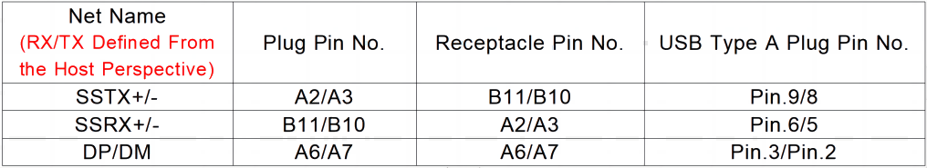
USB Type-C Plug/Receptacle/USB TypeA Pin Correspondence
Type-C Plug/Receptacle/DP network signal correspondence (When designing Type-C Dock, the Tyep-C female connector at the Source side is defined according to “Receptacle Pin No. (female connector on Dock board)
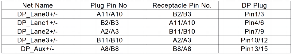
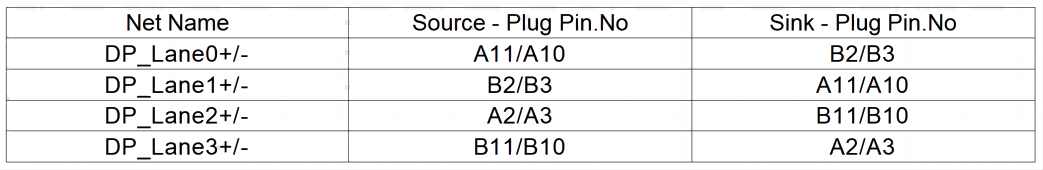
The network corresponding to the male connector of both ends of Type-C (applicable occasion: DP to Type-C, Type-C end is defined in the following table “Plug Pin.)