Since 1998 USB has been released, it has existed more than 20 years. During these 20 years, the USB-IF organization released N kinds of interface statuses, including interface types such as A port, B port, MINI-A, MINI-B, Micro-A, and Micro-B. Due to the different preferences of each product, different products use different types of sockets, so the tragedy is coming, we also need to keep the unusable interface to the wiring material.
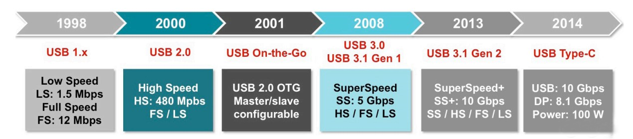
Picture 1 The release time node of USB protocol
For Type-C, it seems that the USB standardization organization is also aware of the issue of unification and standardization. In defining the standard, in addition to the hardware interface definition, a part of the ‘personalization’ feature has been added. What is it?
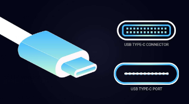
1.1 Defined a new interface form
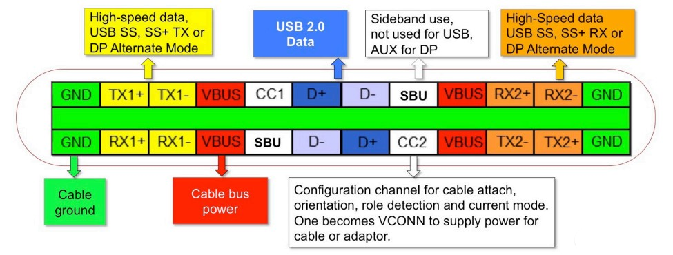
The interface size is similar to that of Micro USB, which is about 8.3mm x 2.5mm. It supports forward and reverse insertion, and also specifies the corresponding wire. The interface is defined as follows (the cable end only has a pair of USB2.0 DATA):

On the socket definition, the following two sockets are defined:
a)Full-featured Type-C socket for platforms and devices that support USB 2.0, USB 3.1, and more.
b)USB 2.0 Type-C sockets can only be used on platforms and devices that support USB 2.0. On the plug definition, the following three plugs are defined:
a)Full-featured Type-C plug for platforms and devices that support USB 2.0, USB 3.1, and more.
b)USB 2.0 Type-C plugs can only be used on platforms and devices that support USB 2.0.
c)USB Type-C Power-Only plugs are used on devices that only require power (such as a charger).
On the cable definition, the following three cables are defined:
a)Full-featured Type-C cable with full-featured Type-C plugs on both ends
b)Both ends are USB 2.0 Type-C cables with USB 2.0 Type-C plugs.
c)Only one end is a cable of Type-C plug (full-featured Type-C plug or USB 2.0 Type-C plug), also defined N kinds of cables for compatibility with older devices:
a)A cable with a full-featured Type-C plug on one end and a USB 3.1 Type-A plug on the other end.
b)A cable with a USB 2.0 Type-C plug on one end and a USB 2.0 Type-A plug on the other end.
c)A cable with a full-featured Type-C plug on one end and a USB 3.1 Type-B plug on the other end.
d)A cable with a USB 2.0 Type-C plug on one end and a USB 2.0 Type-B plug on the other end.
e)A cable with a USB 2.0 Type-C plug on one end and a USB 2.0 Mini-B plug on the other end.
f)A cable with a full-featured Type-C plug on one end and a USB 3.1 Micro-B plug on the other end.
g)A cable with a USB 2.0 Type-C plug on one end and a USB 2.0 Micro-B plug on the other end.
h)An adapter with a full-featured Type-C plug on one end and a USB 3.1 Type-A jack on the other end.
i)An adapter with a USB 2.0 Type-C plug on one end and a USB 2.0 Micro-B socket on the other end.
For the above wires, we know that Type-A is connected to HOST, so in the patch cord, the CC pin needs to be connected with a pull-up resistor. Type-B is connected to Device, so the CC pin needs to be connected to the pull-down resistor.
Among them, the full-featured Type-C should have the E-Marker function. With the E-Marker, the cable can be read with its current capability, characteristics, wire ID and so on. E-Marker’s power supply comes from VCONN. How do you know that the cable needs VCONN? The cable will pass the pull-down resistor Ra, and the source will provide VCONN after detection.
1.2 Transmission rate, Power supply efficiency
The maximum transmission speed is 10Gb/s, which is the USB 3.1 Gen2 standard. It also supports 4 Lane DP mode to transmit high-definition images. In the power supply part, it can support up to 100W (20V/5A).

1.3 ‘personalized’ negotiation mechanism
Because the ports are the same, the interfaces on both ends of the cable are always in the same way. In order to distinguish the roles of the USB devices at both ends (Host/Device), a negotiation mechanism is required to facilitate role confirmation. This part is set by the CC (Configuration Channel) pin. Later with the introduction of the PD specification, the CC pin was used to do simple half-duplex communication to complete the negotiation of POWER supply.
1.4 Strong and unrestrained situation
Due to the extension function of Type-C (SBU1/SBU2), most of the accessories such as headphones, video interface, Debug interface, etc. can be compatible design, successfully countering all previous USB standards, and successfully succeeded!